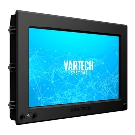
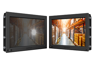
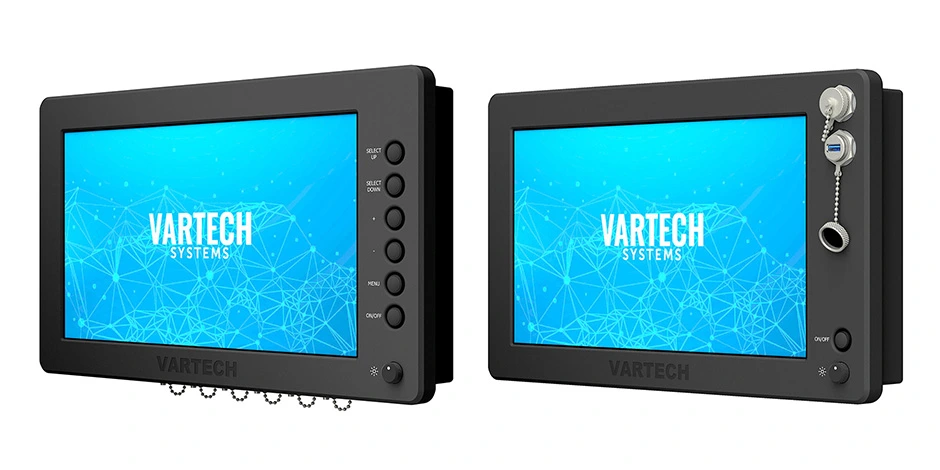
All-Weather computers and monitors include rugged touchscreens built for marine and military applications. Display sizes span 8.4" to 21.5", all built to NEMA 6 and IP67 protection standards.
Operating temperatures range from -40°C to 70°C, depending on configuration, supporting functionality in extreme cold and heat. PCAP, standard resistive, and resistive ArmorTouch configurations all support gloved operation.
DiamondVue computers and monitors offer touchscreen displays from 6.5" to 43", providing interface solutions for the life sciences and food processing industries.
Front-sealed and built with stainless steel faceplates as needed for washdown and clean in place environments, their NEMA 4X and IP66-protected enclosures keep out dust and water and resist damage from corrosive chemicals.

PCAP (projected capacitive) touchscreens respond to multi-touch gestures like swiping, pinching, zooming, and rotating, typically supporting five-point touch.
Operators can navigate complex interfaces efficiently while wearing protective gloves. Their ability to maintain functionality in wet, snowy, icy, and dusty conditions makes them invaluable for harsh environments.
Thick glass overlays or vandal-resistant layers can be added without affecting touch response. Standard resistive and resistive ArmorTouch LCDs resist electromagnetic interference (EMI) when our EMI protection package is applied to meet MIL-STD 461 regulations. With standard resistive, touch functionality will continue uninterrupted even when glass becomes scratched or cracked.
Resistive ArmorTouch touchscreens use glass surfaces rated at ≥7H hardness. They resist scratches, abrasions, water exposure, and chemical contact. These pressure-activated screens work normally even when oil, grease, dirt, or water covers the surface.
Standard resistive touchscreens provide 4H hardness and stable performance for precise control of tasks.
Our standard resistive and resistive ArmorTouch displays support Windows 10, Windows 11, and select versions of Linux.
PCAP and resistive ArmorTouch screens work in facilities requiring frequent chemical cleaning and washdown cycles. Both technologies respond to gloved hands and styluses, meeting food safety requirements where PPE is required.
Chemical resistance and waterproof construction allow for thorough cleaning without LCD degradation.
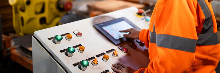
VarTech Systems’ touchscreen monitors and computers serve as human-machine interfaces in facilities running continuous operations. Workers wearing protective gloves use our products to control automation, monitor production, and adjust settings in real-time.
Resistive ArmorTouch technology handles extreme temperatures, moisture, and vandalism attempts. When complemented by our optical bonding process, high-bright displays with responsive touch controls maintain visibility in direct sunlight and bad weather.

Based in Clemmons, North Carolina, VarTech Systems Inc. engineers and builds custom industrial and rugged computers, monitors, and HMIs.